Up Front Controller
UFC
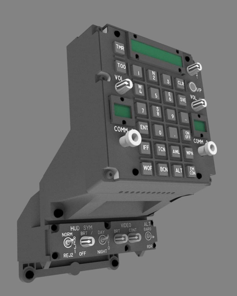
The UFC in the Harrier, or “Up Front Controller”, consists of a keypad, several knobs, and 3 displays. The biggest display is the “scratchpad”, which consists of a bunch of 10 smaller 16-segment characters on the right side, and 3 larger 16-segment characters on the right left side. The real scratchpad used a custom VFD (vacuum Fluorescent Display) where each segment consists of 2-3 dots. The 2 smaller displays are the COMM 1 and COMM 2 radio channel preset selectors. These are also VFD displays, consisting of 2 large 16 segment characters and an extra 2 segment character on the left side that serves as a radio transmit indicator.
Displays
These displays have not been made in a long, long time, and are unobtainable. I’ve tried and tried, and they are simply not available. It should be noted that there are also no off-the-shelf LED displays that exactly replicate these displays. These displays have a non-common design that can’t be replicated with off-the-shelf components. Nobody makes a LED display with 13 characters that have 2 sizes (3 wide characters and 10 narrow characters), let alone a display that uses mostly 3 “dots” to represent each segment.
TEK Creations has something close, but it’s designed for the F-18 UFC, which is different. I looked at their DIY kit of displays and ordered a set, mainly for the ODU. These are custom manufactured specifically for TEK Creations under contract by a LED manufacturer. You can only order those parts from TEK Creations, and they are not cheap. They are also definitely not plug-in-play. You have to buy a special common anode driver chip to make them work, which also requires a lot of extra circuitry and complexity. The displays themselves are also not correct for the Harrier. The F-18 scratchpad has less characters than the Harrier’s scratchpad, does not have 2 different sizes of characters within the scratchpad, and the radio selectors only have a single digit as opposed to the Harrier’s dual digit.
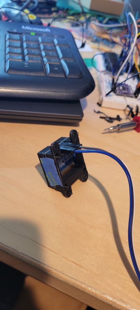
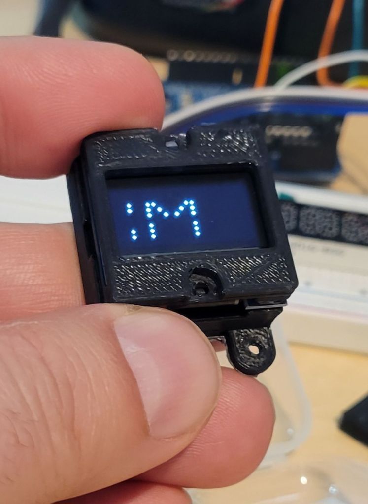
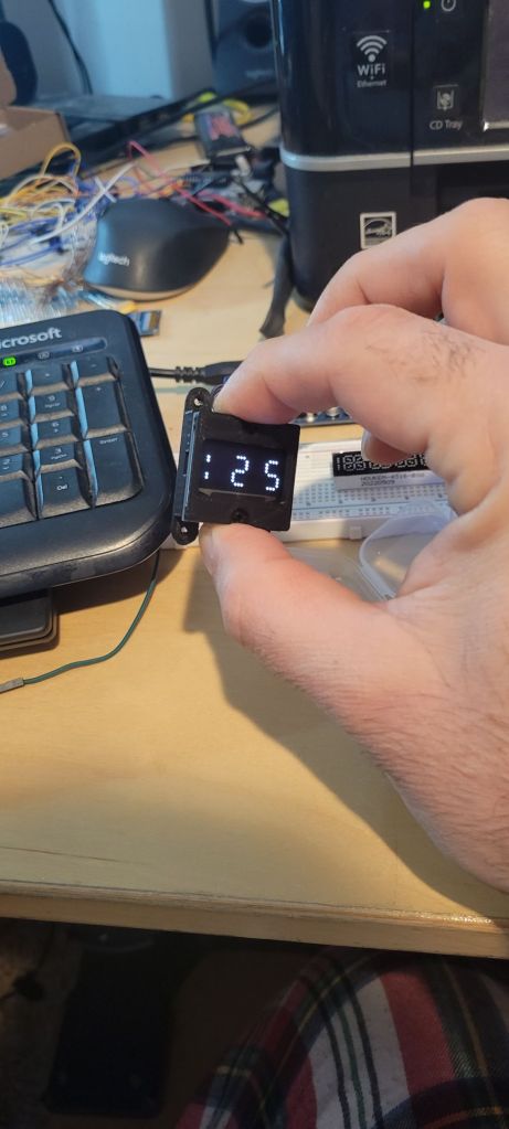
Fortunately, I found an elegant solution that also happens to be very affordable. I was able to simulate the VFD displays using OLED displays, and writing Arduino code to replicate the “dot” appearance using 5 pixels in a star pattern to represent a dot.

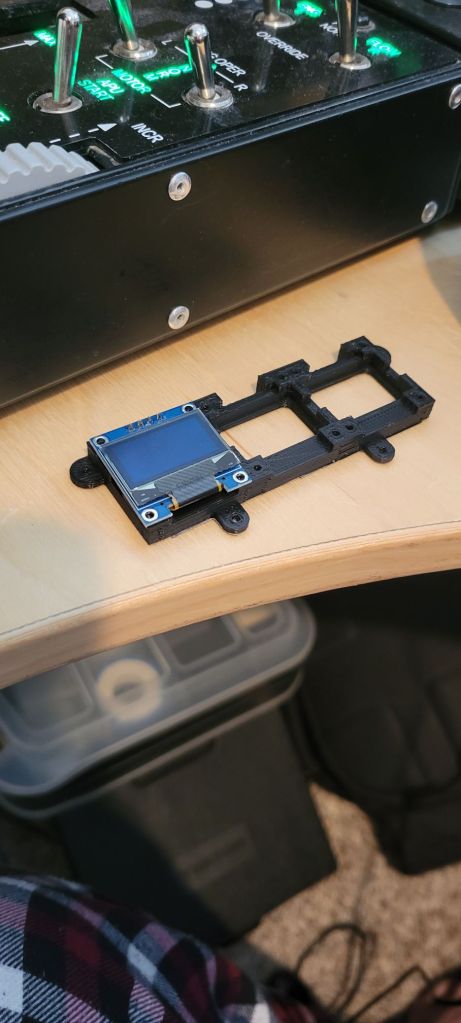
When displayed on the OLED displays, these look like the real thing. I discovered that the off-the-shelf 128×64 pixel OLED displays with i2c interfaces work perfectly for the all 3 displays, and are extremely affordable. I was able to buy a 5-pack of these SSD1306 displays for $14. I use all 5 in my UFC – 1 each for the radio preset selectors, and 3 for the scratchpad. Let me explain the scratchpad. I found that if I combine 3 of them side-by-side, I have the rough width of the scratchpad for the UFC. I was able to write Arduino code to replicate the scratchpad so that it leverages the 3 displays. Yes, there’s a little gap between each display, but I was able to work around that problem so that isn’t very noticeable.

You will notice in the photo above that there is also a purple board with a chip being used. That is an i2c multiplexer. It allows a microcontroller (like an Arduino) to “talk” to open to 8 i2c devices over a single i2c address. There’s a reason for needing this. The SSD1306 displays are all hardcoded to the same i2c address. My cheap displays used 0x3C for the address. I believe the Adafruit ones are 0x3D. The multiplexer, TCA9548A1, is set to a single address. Each display is connected to that board on one of the 8 sets of SCL (serial clock) and SDA (serial data) pins. In order to talk to one of the displays, you first tell the TCA9548A1 to switch to the desired i2c device via an i2c command to the TCA9548A1. Then you send whatever i2c commands needed for the display. When you are ready to switch to the next display, you set the TCA9548A1 to the next one and rinse and repeat until you’ve written to all of the displays. Then you rinse and repeat the next time you need to update the displays. I used a clone of the TCA9548A1 breakout board designed by Adafruit. Here’s more info about the multiplexer from Adafruit:
https://learn.adafruit.com/adafruit-tca9548a-1-to-8-i2c-multiplexer-breakout/downloads
An astute observer will notice that the SSD1306 OLED displays are white, but the real displays in the Harrier are a green color. I’ve thought of that as well. It’s very easy to put a color tint on top of the display to tint the display to any desired color. This is exactly what I’ve done. I used a “forest green” tinted gel that is made for spot lights. You can stack additional gels to darken the color, as I’ve done here:

I would argue that this is the most realistic clone of the Harrier UFC displays out there. Nobody has come closer than this. There are a few Harrier UFC solutions on there, but none of them have accurate displays. They also seem to use standard alphanumeric character displays meant for clocks, and you can tell. I’d agree that it’s an acceptable tradeoff, but I wanted to get as close to the real thing as possible – and I believe I have achieved that.
UFC Body
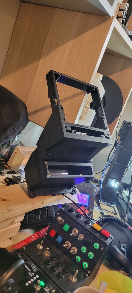
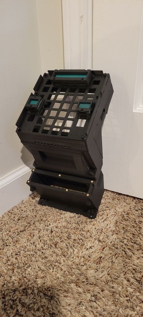
The UFC body is to be 3D printed. I have divided the UFC into sections that can be printed separately and then assembled together into a single unit, which gets bolted into the cockpit. The real unit gets bolted to both the HUD body near the top, and to the main instrument panel near the bottom. There are 5 main parts to the UFC body. Then there is the UFC “tray” that contains the displays, keypad, and knobs.
Microcontroller(s)
One or two, that is the question. I am still debating on whether I will use a single Arduino to operate all of the UFC, or if I will use 2 microcontrollers, one for the displays, and one for the inputs. The reason I might consider using 2 is that there is a bigger chance for input lag if using DCS-BIOS with the keypad. However, if I use a separate controller as a HID device, then there will be zero lag in input, plus I could use the keypad and knobs with other planes without having to swap out the Arduino code to match the plane module that is loaded. There is a high probability that I will go this route. I have yet to design the PCB, however. In order to make it easier to assemble, I will probably base my PCB on off-the-shelf components that utilize the breakout boards, versus designing the PCB to require soldering surface-mount components that are non-trivial to solder. Stay tuned.
PCB
The circuit boards for the UFC consists of a main board and 3 breakout boards that attach to the main board via IDC cables. One breakout board is for the left annuciators and Master Caution switch / light and one is for the right annuciators and Master Warn switch / light. The third breakout board is for the HUD control panel that is below the UFC panel.
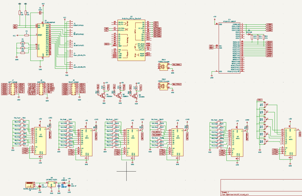
The maon board utilizes an Arduino Micro which will be plugged into a socket on the rear of the board. Because the mainboard will be drawing more current than an Arduino Micro can supply (largely due to driving the 5 OLED displays, the 23 annunciator lights, the 27 keypad lights, and the panel lights), the main board will contain an external power supply jack and onboard voltage regulator.
Here is a first draft of the main board circuit design (which is still missing LED’s for the back lighting):
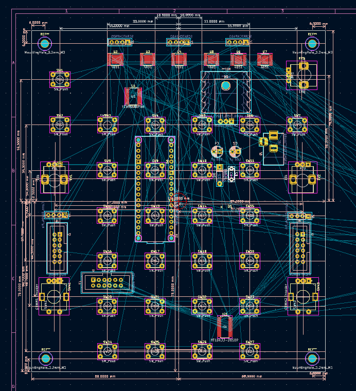
Here is a work in progress for the main board layout:
And here are sone renders of the mainboard:


In September 2024, the first test prints were made.

Stay tuned for completion of the UFC. For now, enjoy some WIP photos: